Smart Weather Station(using Arduino)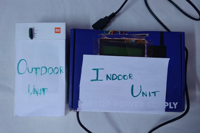
Step 1: Things Required


- Arduino x 2
- HC-05 Bluetooth Module x 2
- 16x2 LCD Display x 1
- DHT 11 x 1
- Breadboard x 2
- Communication Cable


Step 2: What Is the Bluetooth Master and Slave Mode?

Step 3: Converting an HC-05 to Master and Slave Mode:
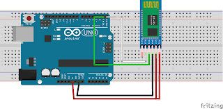
For this project, we need to configure both modules. To do that we need to switch to AT Command Mode and here’s how we will do that. First, we need to connect the Bluetooth module to the Arduino as given in the circuit schematics. What we need to do additionally is to connect the “EN” pin of the Bluetooth module to 5 volts and also switch the TX and RX pins at the Arduino Board.
SLAVE DEVICE:
Now while holding the small button over the “EN” pin we need to power the module and that’s how we will enter the command mode. If the Bluetooth module led is flashing every 2 seconds that means that we have successfully entered the AT command mode. After this, we need to upload the At Command.ino file to the Arduino but don’t forget to disconnect the RX and TX lines while uploading. Then we need to run the Serial Monitor and there select “Both NL and CR”, as well as, “9600 baud” rate which is the default baud rate of the Bluetooth module. Now we are ready to send commands and their format is as follows. All commands start with “AT”, followed by the “+” sign, then a and they end either with the “?” sign which returns the current value of the parameter or the “=” sign when we want to enter a new value for that parameter. Now we should configure the slave module. So for example, if we type just “AT” which is a test command we should get back the message “OK”. Then if we type “AT+UART?” we should get back the message that shows the default baud rate which is 38400. Then if we type “AT+ROLE?” we will get back a message “+ROLE=0” which means that the Bluetooth device is in slave mode. If we type “AT+ADDR?” we will get back the address of the Bluetooth module and it should look something like this: 98d3:34:905d3f. Now we need to write down this address as we will need it when configuring the master device. Actually, that’s all we need when configuring the slave device, to get its address, although we can change many different parameters like its name, baud rate, pairing password, and so on, but we won’t do that for this example.
MASTER DEVICE:
Ok now let’s move on and configure the other Bluetooth module as a master device. First, we will check the baud rate to make sure it’s the same 38400 as the slave device. Then by typing “AT+ROLE=1” we will set the Bluetooth module as a master device. After this using the “AT+CMODE=0” we will set the connect mode to “fixed address” and using the “AT+BIND=” command we will set the address of the slave device that we previously wrote down. Note here that when writing the address we need to use commas instead of colons. Also note that we could have skipped the previous step if we entered “1” instead of “0” at the “AT+CMODE” command, which makes the master connect to any device in its transmission range but that’s less secure configuration. Here you can find a complete list of commands and parameters: HC-05 AT Commands List
Nevertheless, that’s all we need for a basic configuration of the Bluetooth modules to work as a master and slave devices and now if we reconnect them in normal, data mode, and re-power the modules, in a matter of seconds the master will connect to the slave. Both modules will start flashing every 2 seconds indicating a successful connection.
Step 4: Final Assembly :


Step 5: Working:


Keep the slave unit outdoors and the master unit indoors you can monitor the temperature and dew from indoors without going outdoors.
Follow Me @ https://github.com/sanjus-robotic-studio
And Subscribe to my channel : Sanju's Robotics Studio
Code : LINK
Comments
Post a Comment